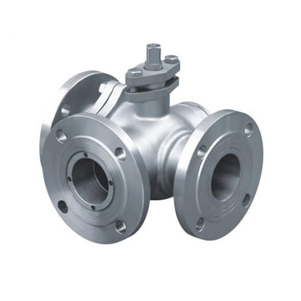
Stainless Steel Flanged 3 Way Ball Valve
- Production Capacity
- 6000 ton/year
- MOQ
- 10 PCS/size
- Pressure
- ANSI CLASS 150-900
- Size
- 1/2~10 inch (DN15~DN250)
- Payment Terms
- T/T, Western Union, PayPal, etc.
- Connection Form
- Flange
- Standard
- ASME16.5/16.34
- Thread Type
- Floating Ball Valve
- Transport Package
- Standard Exporting Plywood Case
- Material
- SS304/316/304L/316L ( CF8/CF8M/CF3/CF3M), WCB, etc.
Stainless Steel Flanged 3 Way Ball Valve
- Thread & Flange Ball Valves, Three Way Ball Valve, Gate Valves, Globe Valves, Check Valves, Y Strainers in stainless steel, carbon steel, cast steel, forged steel and alloy steel.
- Thread 3 Way Ball Valve, Flange 3 Way Ball Valve, T Port Thread 3 Way Ball Valve, L Port Thread 3 Way Ball Valve, Flange 3 Way T Port Ball Valve, Flange 3 Way L Port Ball Valve, Three Way Stainless Steel T/L Port Ball Valve with ISO5211 Direct Mounting Pad.
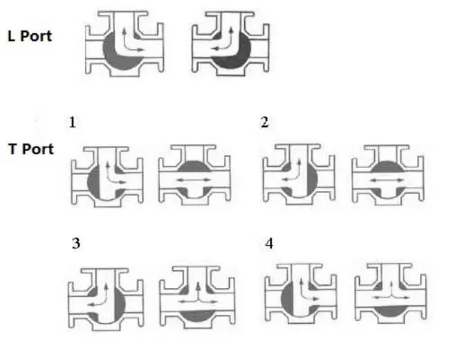
- Three- and four-way have an L- or T-shaped hole through the middle. The different combinations of flow are shown in the figure. It is easy to see that a T valve can connect any pair of ports, or all three, together, but the 45 degree position which might disconnect all three leaves no margin for error. The L valve can connect the center port to either side port, or disconnect all three, but it cannot connect the side ports together.
- Multi-port ball valves with 4 ways, or more, are also commercially available, the inlet way often being orthogonal to the plane of the outlets. For special applications, such as driving air-powered motors from forward to reverse, the operation is performed by rotating a single lever four-way valve. The 4-way ball valve has two L-shaped ports in the ball that do not interconnect, sometimes referred to as an "×" port.
Features and Benefits:
- Balanced 4-Seat Construction
Unlike 2-seated diverter valves, the 509F series has 4 seats (5 seats in bottom entry valves) for positive shut-off in the closed position. This true multiport function can reduce the number of valves required in a process system and gives engineers greater design flexibility
- ISO 5211 Mounting Pad
Standard mounting pad dimensions make it easy to assemble electric or pneumatic actuators
- High-Cycle, Live Loaded Stem Packing
Dynamic loading on stem packing ensures a tight seal through varying pressure and temperature conditions, extending service life and reducing maintenance costs
- Blow-Out-Proof Stem
Stem is bottom loaded to prevent removal when valve is in service
- Full Port Design
Full port construction improves flow characteristics for greater process efficiencies
- Multi-Position Lever Handle
The lever handle can be positioned in two (1/2"-2") or four (3"-4") different orientations for greater piping flexibilit
- 90° or 180° Actuation
Stop plates are available for both 90° and 180° actuation
| Product Name | Stainless Steel Flanged 3 Way Ball Valve |
| 1. Material | SS304/316/304L/316L ( CF8/CF8M/CF3/CF3M), WCB, etc. |
| 2. Size | 1/2~10 inch (DN15~DN250) |
| 3. Connection ends | Flange |
| 4. Port | Reduce Port |
| 5. Working Pressure | 150LB~300LB |
| 8. Working Temp. | -20~300ºC, or according to customer requirements for different industry. |
| 9. Suitable Medium | Water, Natural Gas, Oil and some corrosive liquid |
| 10. Operated | Handle, Lockable handle, Pneumatic Actuator, Electric Actuator. |
| 11.Design & manufacture standard | API6D |
| 12. Pressure & Temp. standard | ASME 16.34 |
| 13. Face to face dimension standard | ASME 16.10 |
| 14. Flange standard | ASME16.5/16.34 |
| 15. Inspection & Testing | API598, API6D |
| 16. Certificate | ISO9001:2008, CE & TS |
| Shipment | |
| Delivery Time | 15~20 Days |
| Package | Standard Exporting Plywood Case |
| Shipping Port | Ningbo/Shanghai, China |
| Shipping Terms | Exw, FOB, CFR, CIF, etc. |
| Payment Terms | T/T, Western Union, PayPal, etc. |
| 30% prepayment, 70% balance paid before shipping or against copy of BL | |
| Country of Origin | Wenzhou city, China |
| Production Capacity | 6000 ton/year |
| MOQ | 10 PCS/size |
Competitive Advantage:
- 18 Months Guarantee for quality.
- OEM manufacturer, print client's LOGO on the valve body.
- Timely delivery. 15 days for standard products. 30 days for non-standard products to make new mould.
- 100% leakage test after assembly.
- As a factory, every production process can be controlled during manufacture.
- Offer inspection & testing reports for raw materials, production process, wall thickness, face to face dimension, pressure test, welding test, painting test, etc.
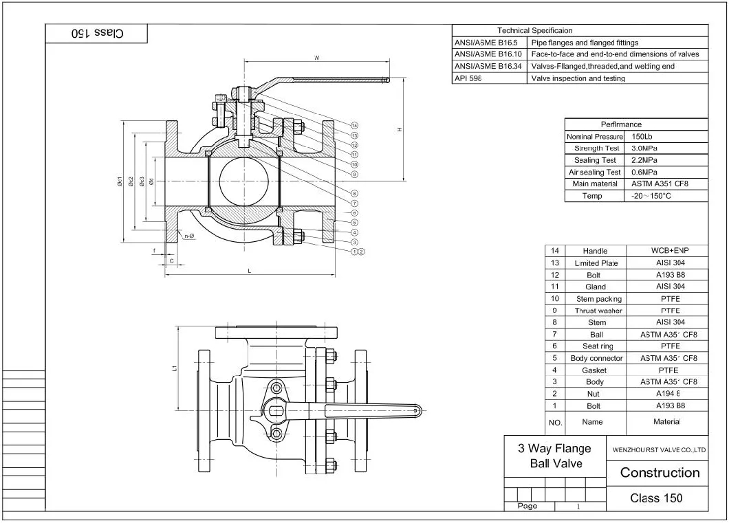
Material List:
| NPS | DN | L | L1 | ¢d | D1 | D2 | D3 | C | F | n-¢ | H | W |
| 1/2'' | 15 | 150 | 75 | 15 | 90 | 60.3 | 34.9 | 9.6 | 2 | 4-16 | 72 | 125 |
| 3/4'' | 20 | 160 | 80 | 20 | 100 | 69.9 | 42.9 | 11.2 | 2 | 4-16 | 78 | 145 |
| 1'' | 25 | 180 | 90 | 25 | 110 | 79.4 | 50.8 | 12.7 | 2 | 4-16 | 88 | 180 |
| 1-1/4'' | 32 | 200 | 100 | 32 | 115 | 88.9 | 63.5 | 14.3 | 2 | 4-16 | 95 | 180 |
| 1-1/2'' | 40 | 220 | 110 | 38 | 125 | 98.5 | 73 | 15.9 | 2 | 4-16 | 110 | 240 |
| 2'' | 50 | 240 | 120 | 50 | 150 | 120.7 | 92.1 | 17.5 | 2 | 4-19 | 120 | 240 |
| 2-1/2'' | 65 | 260 | 130 | 65 | 180 | 139.7 | 104.8 | 20.7 | 2 | 4-19 | 140 | 300 |
| 3'' | 80 | 280 | 140 | 78 | 190 | 152.4 | 127 | 22.3 | 2 | 4-19 | 155 | 350 |
| 4''' | 100 | 320 | 160 | 100 | 230 | 190.5 | 157.2 | 22.3 | 2 | 8-19 | 180 | 350 |
| 5'' | 125 | 380 | 190 | 125 | 255 | 215.9 | 185.7 | 22.3 | 2 | 8-22 | 250 | 500 |
| 6'' | 150 | 440 | 220 | 150 | 280 | 241.3 | 215.9 | 23.9 | 2 | 8-22 | 270 | 600 |
| 8'' | 200 | 550 | 275 | 200 | 345 | 298.5 | 269.9 | 27 | 2 | 8-22 | 300 | 800 |
Note: All the data should be confirmed with the approved drawings of manufacturer.
